Livestock filtration · Design

A filter is only as good as the building around it.

Filter resistance moves the operating point along the fan curve. Where it lands is set by the fans, inlets, and openings already in the building. Sized against each other, those components hold the design airflow with the filters in. Sized in isolation, they work against each other and the barn runs short of air with every part performing exactly as rated.

Contact us Research library
The engineering challenge

Filter count is one question. System performance is another.

Published sizing methods treat filter count as a take-off: divide the barn's maximum ventilation rate by a standard CFM per filter and round up. The arithmetic is straightforward. The assumptions underneath it are where the work is.

MERV rating shifts the CFM a filter passes. Adding a prefilter shifts it again. The same MERV rating from two different manufacturers can differ by 100 to 200 CFM per filter. A count derived from a generic design value may be off before a single component is installed.

And filters may not be the bottleneck at all. Ceiling inlets, evaporative pads, soffits, and exterior air intakes all add resistance to the same system the fans are fighting. A correctly sized filter bank in a building with inadequate inlet area still underperforms. So does one with undersized cool cells or insufficient soffit or dormer intake on the exterior.

What we do is evaluate the complete system, not the filter count in isolation.

1

Fan curve

Every fan delivers less CFM as static pressure increases. This relationship is documented in manufacturer performance curves and is not linear, small pressure increases can produce significant CFM reductions at certain operating points.

2

Filter resistance

Filters add static pressure to the system. The amount depends on face velocity, lower velocity means lower pressure drop. More filter face area distributes the airflow and reduces resistance per filter, but increases capital cost and structural requirements.

3

System equilibrium

The real operating point, where the building actually runs, is where the fan performance curve intersects the total system resistance curve. That point is different from any individual component's rated condition and requires the full system to be modeled together.

4

Inlet interaction

Inlets, curtains, and existing openings also affect system pressure. A building with too much or too little inlet area relative to filter and exhaust capacity creates pressure imbalances that defeat the filtration design regardless of filter quality.

How we build the model

The answer is not to avoid filtration or accept reduced ventilation, it is to design the complete system with the filter in place from the start, using actual manufacturer performance data for fans, filters, and inlets rather than rated values at a single static pressure point. When the model uses real component curves and solves for the equilibrium operating point, the design accounts for how the system actually behaves, and specifications can be adjusted before anything is installed rather than after performance falls short.

How we design filtration systems

Built from the numbers up.

Every filtration design we produce starts with measuring what the building currently does and modelling what it needs to do with filters installed. Specifications come out of that model, not out of rule-of-thumb matching.

01

Ventilation audit

Fan inventory and actual delivery at real static pressure, inlet type and total length, air exchange rate, room volume and animal density. Starting from current performance, not design intent.

02

System modelling

Fan performance curves, filter pressure drop curves, and inlet characteristics are used to find the actual operating point for the filtered system. Target CFM and air exchange are verified against animal welfare requirements before specifications are set.

03

MERV selection

Filter class is matched to pathogen pressure, herd or flock value, and what the ventilation system can absorb in added static pressure. The choice is documented and justified, not assumed from convention.

04

Buildable drawings

Filter count and size by room, fan and inlet specification, plenum or attic box framing detail, and seal requirements. Drawings a contractor can price from and install from, not a concept requiring field interpretation.

highlowlowhigh STATIC PRESSURE (in. w.c.) AIRFLOW (CFM) FAN no filter + filters OP1 OP2 CFM REDUCTION
Operating point
OP1
System resistance
Base
CFM delivered
Design
Static pressure
Design
Dual-stage filtration

Where a prefilter is used, the system carries the resistance of both stages, and the two do not simply add. How the prefilter and the main filter interact at their shared face depends on the pairing and the spacing between them, which is why the combined figure has to be established for the system being built rather than taken from a specification sheet. The case for and against running prefilters at all is set out on the filters page.

System design

Negative and positive pressure filtration: how each works and what each requires.

Both approaches reduce airborne pathogen introduction. Which fits a given farm depends on the building, the operation, and what the producer is prepared to design and maintain for. Dynamic Innovations works with producers on both approaches and helps identify the right fit before anything is specified.

Negative pressure filtration

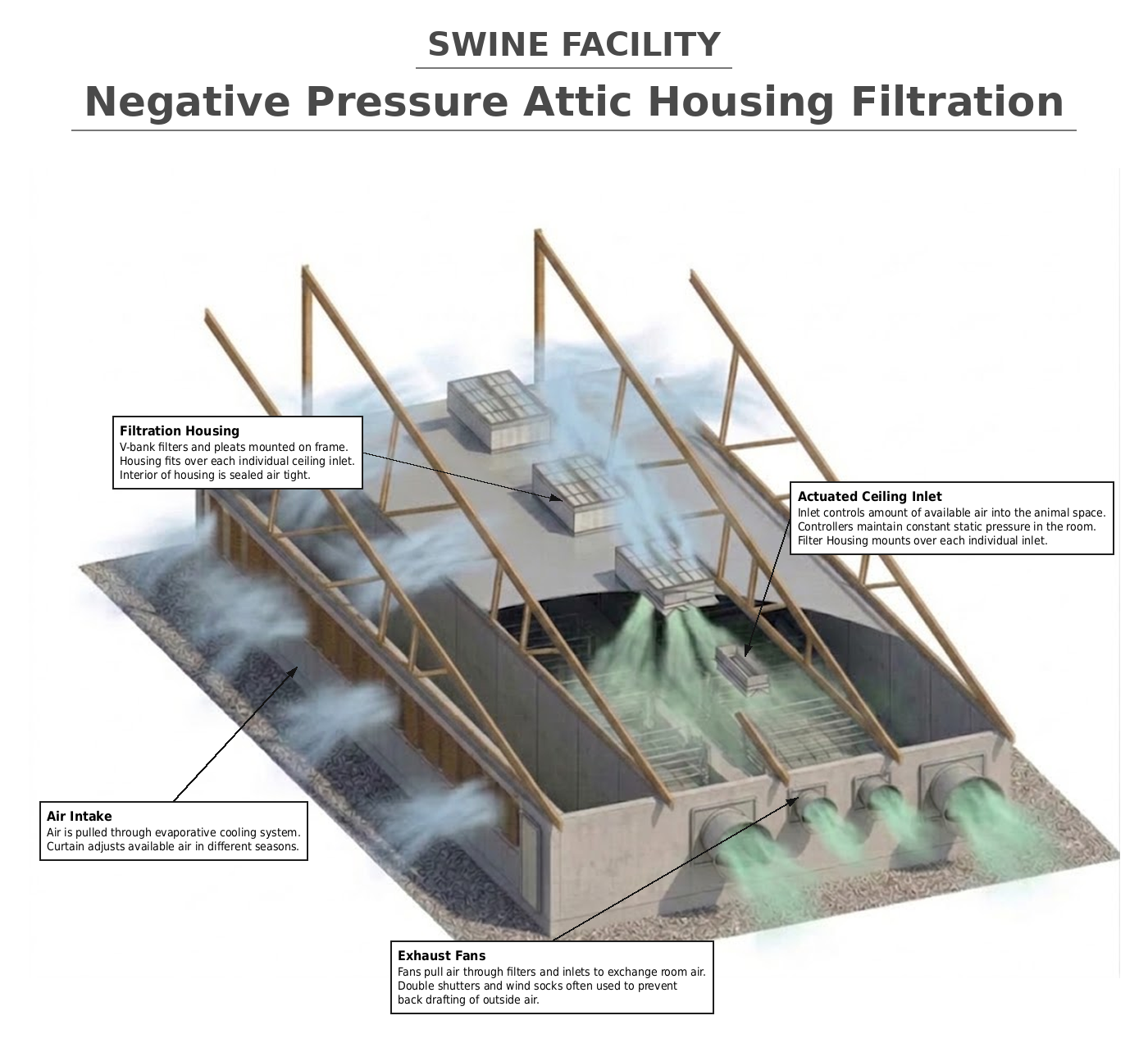
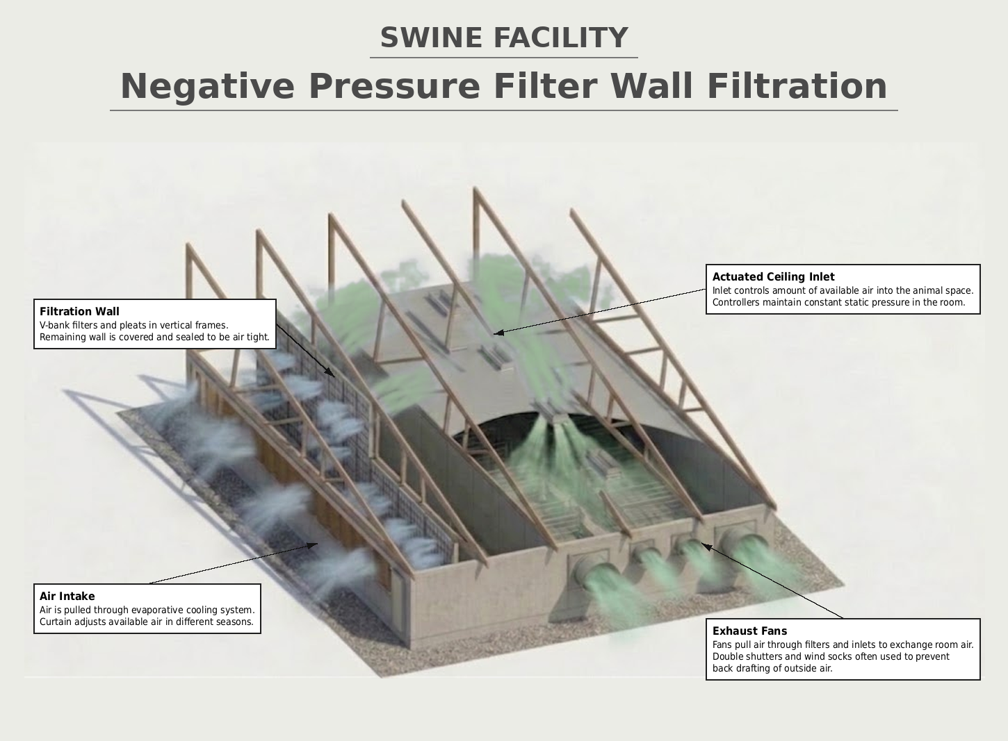
Exhaust fans pull air from the animal space, creating a slight vacuum inside the barn relative to outside. That vacuum draws fresh air inward through the inlet system. In a filtered negative pressure barn, filters sit at the inlets: either in individual attic housings over each ceiling inlet, or in a filter wall that treats the entire incoming air supply before it enters the attic. The barn and attic operate at lower pressure than outside.

Negative pressure is the dominant system in North American swine production. Ventilation controls are simpler, fan staging is straightforward to troubleshoot, and the system works with existing building layouts. Adding filtration to a negative pressure barn is the most common retrofit scenario and is well understood in the field.

The challenge is infiltration. The vacuum inside the barn draws air in through any opening that is not sealed: louvers on idle fans, gaps in curtains, cracks around doors, pit covers, and any other unplanned opening. In a filtered barn, every one of those openings is an unfiltered air inlet. Managing them is ongoing, and the consequences of missing one are real.
Negative pressure · attic housings
Cutaway of a swine barn with filter housings mounted over each ceiling inlet, air entering through a sidewall evaporative cooling pad and leaving through end wall exhaust fans.
Filters at each ceiling inlet A housing sits over every inlet, so the attic carries unfiltered air and each inlet filters its own share of it. Filter count follows inlet count, and any leak in a housing bypasses that inlet entirely.
Negative pressure · filter wall
Cutaway of a swine barn with a full sidewall filter bank feeding the attic, plain actuated ceiling inlets, and end wall exhaust fans.
Filters at the wall, plain inlets at the ceiling The entire incoming supply is treated before it reaches the attic, so the attic itself is clean and the ceiling inlets do nothing but distribute. Fewer sealing surfaces to maintain, and the filter bank is reachable without entering the attic.

Positive pressure filtration

Supply fans push filtered air into the barn, creating slightly higher pressure inside than outside. Fresh air enters only through the filter bank. Air exits through designated exhaust openings: actuated curtains, wall exhaust ports, or passive outlets. The attic and animal space are at positive pressure relative to outside.

The biosecurity argument for positive pressure is that infiltration works in the system's favour. Any gap in the building envelope exhausts filtered air outward rather than drawing unfiltered air inward. The barn does not have to be sealed perfectly to maintain biosecurity. It has to maintain enough pressure differential to keep air moving outward through every gap.

The tradeoffs are real. Positive pressure pushes warm, moist barn air through every opening in the building shell, which accelerates structural deterioration over time. Controls are more complex. The system has less margin when equipment fails, and capital cost is generally higher. These factors explain why positive pressure remains less common than negative pressure despite its biosecurity advantages on paper.
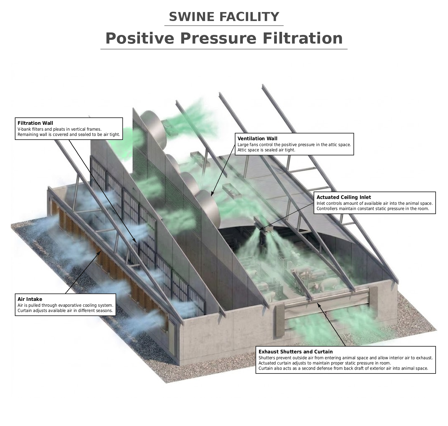
Positive pressure
Cutaway of a swine barn with supply fans pushing filtered air into a sealed attic plenum, air leaving through actuated exhaust shutters and curtain.
Supply fans pressurise the attic Air is filtered, then pushed rather than pulled. The attic and animal space sit above outside pressure, so gaps in the shell exhaust outward instead of drawing in. Exhaust is through actuated shutters and curtain rather than fans.

MERV selection ties directly to system type. A negative pressure barn with uncontrolled infiltration is filtering a smaller fraction of its total incoming air than its filter count suggests. A positive pressure barn maintaining good pressure differential is filtering a higher fraction than an equivalent negative pressure installation with average sealing. The MERV specification is a floor. The system design determines how much of the time that floor is actually in effect.

What the field record says about choosing between them

Sixteen years of monitored US sow farm data, covering 245 unfiltered and 178 filtered farms from 2009 to 2024, gives the clearest answer available. Filtered herds ran roughly half the PRRS incidence rate of unfiltered herds. That held for negative pressure and it held for positive pressure, and it held for year-round filtration and for seasonal filtration alike.

It is tempting to read a ranking into the individual figures, and it would be a mistake. Each pressure type was measured against unfiltered farms, not against the other. When the study compared positive directly against negative, the difference was inconclusive, and in the most recent five-year period negative pressure carried the lower rate. Only 47 positive-pressure farms were in the dataset. The honest conclusion is that both work, and the choice between them is a retrofit, sealing, structure and maintenance question rather than an efficacy question.Yue et al., Animal 2026, article 101834
Backdraft and barn sealing

A filtered barn is only as effective as its weakest unfiltered air path.

Filtration is a system, not a component. Whatever enters the barn without passing through a filter is unfiltered air, regardless of what the filters are rated at.

Building infiltration

Every barn leaks. Curtain gaps, pit covers, cracks around doors and windows, worn panel seams: all become unfiltered inlets in a negative pressure building. These are not catastrophic failures individually, but collectively they represent a meaningful fraction of total incoming air in some facilities, and that fraction is entirely unfiltered. Sealing work at installation is the first line of control, but barns are not static structures. Building movement, settling, weathering, and equipment installation all create new gaps over time. Annual inspection of the building envelope is as much a part of operating a filtered barn as changing filters on schedule.

Three categories of barn air infiltration matter in practice. Inflow is outside air entering through fans or doors and mixing directly with inside air, the primary disease transmission concern. Interflow is air moving between internal rooms, such as from shower areas or offices into the production space. Short-circuiting is outside air entering but failing to mix, running along the end of pens nearest the fans while the rest of the barn air is largely undisturbed. All three affect static pressure, air distribution, and the effective protection the filter system provides.

Fan backdraft

When an exhaust fan shuts off, its louvers are supposed to close and seal the opening. In practice they rarely seal completely, and the vacuum inside a negative pressure barn actively pulls outside air back through any louver that is not fully seated. A partially open or stuck louver on an idle fan is an unfiltered air inlet sized to the full diameter of that fan. Louvers corrode and stick, springs weaken, ice forms in cold weather, and debris holds blades open: all common maintenance failures that compound over time. Dirty or rusted shutters also reduce airflow capacity on running fans, adding a performance penalty on top of the sealing problem.

Several approaches address this. Double shutters and wind socks provide a secondary closure over the exterior fan face. Purpose-built backdraft dampers create a tighter mechanical seal when the fan stops. Fans that run only in warm weather can be physically sealed, with insulated panels or heavy plastic over the louver face, during idle months. Fan banks take a more structural approach: exhaust fans are grouped into a chamber separated from the animal space by its own sealed wall, drawing through louvers in that wall rather than directly from the pens. The chamber runs at a slight negative pressure of its own, so a fan that fails with its shutter stuck open feeds the chamber rather than the barn, and a running fan in the same bank pulls that air back out. Holding that condition is what the design has to get right. In some instances a curtain over the louvers opens only as far as the fans in operation require, which keeps the chamber ahead of what a stuck shutter can push into it. Left wide open at minimum ventilation, a single large fan backdrafting can overwhelm the small fans running and put outside air into the animal space. The fan bank approach manages backdraft at the system level and is most practical in new construction or significant retrofit where the fan wall can be designed for it. Backdraft is a risk in any filtered barn regardless of system type. The louver and damper discipline required is ongoing maintenance, not a problem solved at installation.

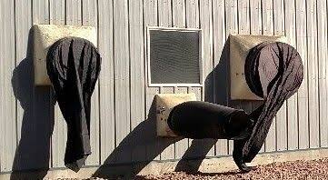
Three fans on a barn sidewall: a small minimum ventilation fan running with its air chute inflated, and two larger idle fans with their chutes pulled flat against the openings
Air chutes on the exterior fan faces. The small minimum ventilation fan below is running and its chute is inflated. The two larger fans are off, and the vacuum the running fan holds on the barn has pulled their chutes flat against the openings, closing the path a loose shutter would otherwise leave open.
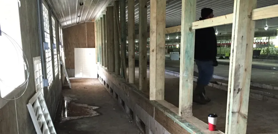
Interior of a fan bank chamber under construction, exhaust fans in the exterior wall at left and louver framing into the animal space at right
Inside a fan bank chamber during construction. Exhaust fans sit in the exterior wall on the left. The framing on the right holds the louvers that draw from the animal space, with a curtain over them that opens only as far as the fans in operation call for. Metering the opening is what keeps the chamber negative to the barn at every stage, including minimum ventilation.

Transition spaces

Load-outs and offices present a different challenge from building infiltration. They are not gaps in the envelope. They are intentional openings operated under constant human traffic. The load-out opens directly to outside air and to trucks that may carry contamination. The office connects to outside through its own HVAC, exhaust vents, and supply entry, and to the production space through interior doors. Many operations treat the office as a permanently compromised zone rather than a filterable one.

The practical approach at transition spaces is localized pressurization: supply fans force filtered air outward through the opening so that when a door opens, air moves from the filtered interior toward the exterior rather than the reverse. This targets the specific entry point without requiring the entire barn to operate under positive pressure. Entryways are commonly purged after doors close to clear any outside air that entered during the open period before it can migrate into the animal space.

Retrofitting a filter wall

Most filtration goes into a building that was not designed for it.

An existing barn has no room for a filter bank. The wall is the wall, and the intake area a filtered system needs is larger than what the building was built with. Adding filtration means building that area onto the outside: dormers along the sidewall, or an extension off the gable end, framed to carry the filter grids and feed the intake behind them.

Sizing one is a two-sided problem. The filter count sets a minimum face area, but the structure also has to deliver that air into the attic, and the throat where it passes through the existing wall is fixed by the building. A dormer sized only to the filter schedule can end up feeding a throat too small to pass what the filters can supply, at which point the restriction moves from the media to the opening and the fans work against the building instead of the filters. Both numbers have to be run before the footing is laid out.

The other thing the drawing has to solve is the transition, where new structure meets a wall that was poured years earlier and has to finish air tight.

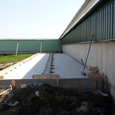
Concrete foundation poured along an existing barn wall with anchor bolts set for a filter wall dormer
Dormer foundation. A new footing poured against the existing sidewall to carry the filter wall. Its footprint follows from both numbers: the face area the filter count requires, and the throat available to move that air into the attic.
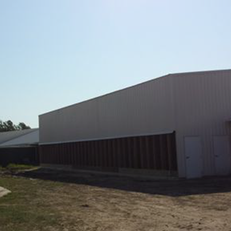
Exterior of an existing barn with a filter wall dormer added along the sidewall
Dormer closed in. The added intake area is enclosed and ready for grids. Siting matters: a bank placed near an exhaust outlet loads faster and loses filter life.
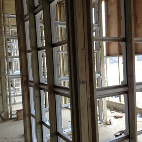
Filter grids set into the dormer framing during a retrofit
Grids in the dormer. The grid and the framing have to agree to the fraction of an inch, and the gasket has to still be doing its job in year five. Air that bypasses a filter through an unsealed penetration is unfiltered air, whatever the media is rated at.
Get in touch

Start with the building you already have.

Whether it is a retrofit, a new build, or a system that has been in for years and is not performing as expected, the conversation starts with what you have.

projects@dynamic-innovations.com 605.237.5869