Livestock filtration

A MERV rating describes a new filter on a test bench. The barn is the rest of the story.

What a MERV rating is measuring, what changes about that filter once it is in service, and what the body and the grid holding it have to do to keep the rating intact.

Contact us Research library
Media type

Two filters can share a MERV rating and not share a service life.

Two filters can carry the same MERV number and behave nothing alike once they are installed. The difference is how they catch particles in the first place, and dusty, humid air treats the two methods very differently.

Mechanical (depth media)

Picture a stack of screens, each finer than the one before it. The first takes the coarse material, the next takes what got through, and so on down the stack. A mechanical filter works on that principle, except the screens are a deep mat of fibres rather than flat mesh, and particles get caught three different ways. Heavy ones carry too much momentum to follow the air around a fibre and run straight into it. Mid-size ones follow the air but brush a fibre on the way past. The very small ones do not travel in a straight line at all, they bounce off course and wander into a fibre on their own. Depth is what makes it work: anything that slips through the first layer still has more layers ahead of it.

Loading makes it better before it makes it worse. Captured dust narrows the gaps and becomes part of the screen, so efficiency climbs across the filter's life instead of falling. The limit is airflow. Every particle held is a little less open area, resistance rises, and eventually the filter chokes off the air the building needs. That end point is predictable, it shows up as static pressure, and it is why a mechanical filter gets changed on a pressure reading rather than a guess.

Preferred for livestock production

Electrostatic (charged media)

Charged fibres pull particles out of the airstream that would otherwise have sailed past. Two things happen at once: particles already carrying a charge are drawn in directly, and neutral particles get polarised by the field and then attracted. Either way, the charge only gets the particle to the fibre. What holds it there afterward is the same surface adhesion that holds it on a mechanical filter.

That distinction is the whole story. The charge is not a grip, it is a reach. It lets thinner, more open media behave like something far denser, without the resistance that density would normally cost, which is why an electret filter of a given rating starts out easier to pull air through. It also means the entire advantage rests on the charge surviving, and the charge is the part that does not last.

Nothing about it is powered. The charge is put into the plastic fibres during manufacture and simply stays there, which is why the media is called an electret: the electrical equivalent of a permanent magnet. There is no switch, no indicator, and no way to tell from the walkway whether it is still doing anything. It is a property of the material, and like any stored charge, it drains.

Performance degrades in production environments

Two filters, three frames

The left frame is a denser mechanical mat. The middle and right are the same electret mat, thinner and more open, shown new and after the charge is gone.
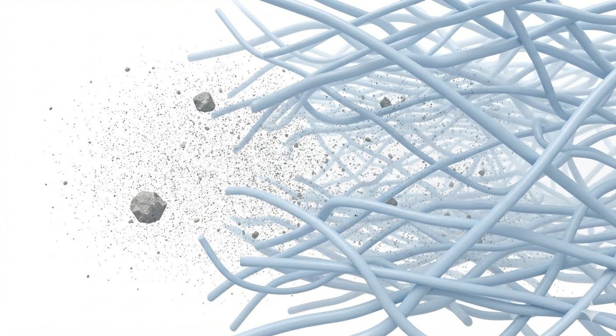
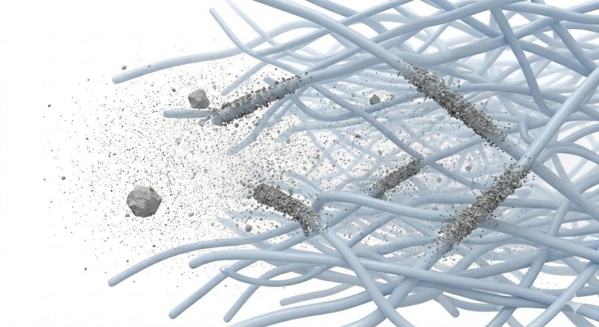
Bare pale blue filter fibres with fine dust caught throughout the depth of the bed. Mechanical
Caught by contact, at every depth Dust collects right through the bed rather than only on the face. Nothing here can wear out, and the captured material becomes part of the filter.
The same fibre bed with dark filaments radiating from several fibres and dust piled heavily along them. Charged, new
The charge reaches into the airstream Particles that would have flown past are pulled onto the fibres carrying charge. This is real performance, and it is what the filter is sold on.
The same fibre bed with the radiating filaments gone, the heavy dust deposits still present on the fibres. Charged, spent
Same filter, no reach left The field is gone. The dust it already caught stays put, so the wall looks no different and the pressure drop barely moves. What it can catch from here is whatever the bare fibres can catch.

The middle and right frames are one mat, before and after. The left frame is a different mat that never had a charge to lose. All three can carry the same MERV on a box. Only one of them still earns it after conditioning.

When the charge goes, nothing looks wrong

Charge loss is not a theory. Raynor and Chae followed electret filters installed in the air handling system of a large building, drawing directly on outdoor air, and watched efficiency fall from 85% to 45% in service. A separate study loaded electret media with cigarette smoke and measured efficiency dropping from 92.5% to 33.3%.

Read that second result carefully, because it contains the warning. Efficiency collapsed by nearly two thirds and the pressure drop did not move. A manometer would have shown a filter in perfect health. Charge loss produces no restriction, no noise, no visible change on the wall. Mechanical filters tell you when they are finished. A discharged electret does not.

Live animal production is a hard case for charged media on nearly every count the research identifies. The filters are drawing outdoor air, whether they sit in attic boxes over the inlets or in a wall, the same exposure that drove the Raynor and Chae result. It runs in heavy submicron dust. Humidity is high by design, and cool cell operation puts saturated air across the media for months at a time. Heat combined with humidity accelerates charge release in the laboratory, and dust loading shields the fibre charge whether or not anything chemical is happening.

None of which stays theoretical. Reviewing filtration across 85 farms, a veterinarian at Swine Vet Center pulled used filters of both types out of hog buildings and had them tested for efficiency at certified laboratories. The finding: fiberglass filters hold their efficiency far longer than synthetic ones, against client budgets that had commonly assumed two to three years of filter life. Fiberglass is mechanical media. Synthetic is where charged media lives. The recommendation that followed was fiberglass at MERV 15 or 16.

There is also a subtler problem inside the loading curve itself. As an electret filter accumulates dust, two failures compound. The charge gets shielded by deposited particles and starts to fade. But the dust cake is not yet thick enough to act as a mechanical filter in its own right. The filter passes through a performance trough mid-life where neither mechanism is fully working. Eventually the growing dust cake does begin helping, and efficiency partially recovers. But it recovers to the mechanical floor, not to the original charged rating. In other words, the MERV-A figure is not only the end state, it is close to the floor the filter passes through during the middle of its service life. The headline MERV is new filter performance. The mechanical floor is the performance the filter will spend most of its working life near.

Where the bank sits on the building matters too. Smith and colleagues found the worst case for filter lifespan is a filter bank with an intake in the immediate vicinity of a barn's exhaust outlet. That is a design and siting finding, not a filter defect, and it lines up with what has been seen in the field: charge largely gone inside about a year, and worst on wall sections positioned where exhausted pit air could find its way back to the intake.

The mechanism is not settled and is not worth guessing at. What matters for a buying decision is the pattern: the loss shows up widely, and it does not show up evenly. Two sites running the same filter do not necessarily land in the same place. An inconsistent failure is worse than a predictable one, because it cannot be scheduled around and it will not announce itself.

Four questions to settle before a charged filter goes in the wall

The four terms used below, in plain language

MERV is the American rating, from ASHRAE 52.2. The filter is tested as it comes out of the box, charge and all.

MERV-A is the same test run a second time after the lab deliberately strips the charge out of the media. It answers one question: what is left when the charge is gone. The step is optional, so a manufacturer only has the number if they paid to find out. It is written as a pair, so MERV 14 / 11A means fourteen new and eleven discharged.

ISO 16890 is the international standard used across Europe and much of the rest of the world. It does the same thing MERV-A does, but does not make it optional: stripping the charge is simply part of how a filter gets classified.

ePM1 and ePM2.5 are what ISO reports instead of a single number. ePM1 is performance on particles up to 1 micron, ePM2.5 up to 2.5 micron. Because of the discharge step, either figure already has the charge loss built into it.

Charged media is not disqualified by any of this. It is disqualified by being bought on the headline number alone. Four steps settle it.

1. Ask for the discharged rating in writing. Under ASHRAE that is the MERV-A figure. Under ISO 16890 it is any ePM1 or ePM2.5 class, which already carries the discharge step. Either standard answers the question, so ask for whichever one the supplier tests to.

2. Treat a refusal as the answer. Appendix J is optional under ASHRAE, so no manufacturer is required to publish MERV-A, and a salesperson promoting charged media may not offer it unprompted. A supplier who tests to ISO already has the discharged number. A supplier who cannot or will not produce one for a charged filter is asking to be bought on the new rating alone. That is a reason to walk.

3. Decide whether the floor is acceptable, before the money moves. MERV 14 is not an arbitrary line. Using a dual chamber model, Dee and colleagues found a mechanical MERV 14 filter prevented airborne PRRSV spread at concentrations of one million TCID50 per litre and below. But the recommendation scales with where the building sits: published guidance puts MERV 14 as the secondary filter recommendation for low density swine regions, with MERV 15 or 16 for high density areas. The efficiency gap behind that is real, with MERV 16 and MERV 14 measured at roughly 95% and 75% respectively on particles between 0.1 and 0.3 micron. So a MERV 16 that discharges to 14 may be a defensible trade in a sparse region and a poor one in a dense one. A MERV 16 that discharges to 10 or 11 is a different filter than the one specified, anywhere.

4. Test used filters for efficiency, not just airflow. If charged media is already in the wall, pressure readings will not find this. Guidance calls for efficiency testing at least annually, and more often where a synthetic secondary filter is in use. Testing does not mean pulling the whole bank either: Smith and colleagues found a sample of 5.5% of the filters in a bank is representative for positive pressure barns. Airflow monitoring, the right tool for mechanical media, is precisely the instrument that will not warn you here.

What a MERV rating is measuring

A filter catches big particles one way and small particles another way. Big ones cannot turn fast enough to follow the air around a fibre, so they hit it. Really small ones do not travel in a straight line at all, they jitter around and wander into a fibre on their own. In between sits a size that is bad at both: too light to run into anything, too heavy to wander much. That size lands right around 0.3 micron, and it is the single hardest thing a filter will ever be asked to catch. It has a name, the Most Penetrating Particle Size, and it is where ASHRAE 52.2 runs the test. In other words, a MERV number is a filter graded on its worst particle, on its worst day.

That matters for what you get in the barn. A MERV 16 filter holding 95% at 0.3 micron is not 95% overall, it is 95% at the toughest point on the curve and better on both sides of it. The PRRS virion measures 0.05 micron, far below the test particle, in the range where the wandering effect gives filters some of their best performance. But bare virion size is not the target. Airborne pathogens travel attached to droplet nuclei, dust, and respiratory secretions, and the carrier is what reaches the filter. Which band a given pathogen's carrier falls into, and what has actually been measured rather than assumed, is the subject of the next section. A MERV rating is a floor, not a ceiling, and the carrier size is what determines how much headroom is above it.

The controlled work backs that up, including where the floor sits. A four-arm challenge study ran PRRSV aerosol against HEPA, a 95% DOP 0.3 micron filter, bag filtration alone, and an improvised low-cost stack of mosquito netting with two fiberglass and two electrostatic furnace filters. Ten replicates each. HEPA transmitted in none. The 95% DOP filter also transmitted in none, matching HEPA without HEPA's cost or pressure penalty, which is the result that made barn scale filtration a practical proposition. Bag filtration alone failed in two of ten, and that bag was rated MERV 14. The low-cost stack failed in four of ten. All ten controls transmitted, so the challenge was working. Cheaper media is not a discount on the same outcome; it is a different outcome, and a MERV number on its own does not settle the question either.Dee et al., Canadian Journal of Veterinary Research 2006;70(3):168-175. Filter classes stated in EN 779 and EN 1822 era terms; carry the scheme name when quoting them.

E1, E2, E3: where the number actually comes from

A filter test does not produce a single result. The lab counts particles upstream and downstream across twelve size ranges, then collects those into three bands:

E1  0.3 to 1.0 µm
The submicron band. Bacteria, smoke, and the fine end of what a filter is asked to stop.
E2  1.0 to 3.0 µm
Fine particulate. Mould spores, fine barn dust, and much of what carries pathogen.
E3  3.0 to 10 µm
Coarse particulate. Larger dust and the material that loads a filter fastest.

The filter's average efficiency in each band goes against the MERV table, and then comes the part worth knowing: the MERV assigned is the lowest of the three. A filter that performs beautifully on coarse dust and moderately on fine particles is graded on the fine particles. The rating is deliberately built around the weakest result, not the flattering one.

Set the three classes that matter for live animal production side by side and one thing stands out. E1 is the only column that moves. A MERV 14 and a MERV 15 are required to do exactly the same thing in E2 and E3.

What the class requires, minimum
ClassE1E2E3
MERV 1475%90%95%
MERV 1585%90%95%
MERV 1695%95%95%

ANSI/ASHRAE 52.2-2017, Table 12-1.

What two filters might actually measure
BandMERV 14 ExampleMERV 15 Example
E178%86%
E296%91%
E399%95%

Illustrative figures, not a test report and not a product.

Both filters in the second table are legitimately rated. The one on the left cleared the MERV 14 bars and kept going; the one on the right cleared the MERV 15 bars and stopped near them. On the frame, 15 beats 14. On the carrier-sized particles in E2 and E3, the MERV 14 is the better filter. The class number tells you what a filter is guaranteed to do, and only the test report tells you what it actually did. That is why two filters carrying the same rating are not interchangeable, and why the report is worth asking for.

Test reports can be dense. We’ll walk you through yours.
The carrier particle

Two sizes matter, and they are not close to each other.

The first size is the organism itself. The second is the particle it rides on: a respiratory droplet nucleus, a skin cell, a fragment of feed or bedding dust. Airborne pathogens travel attached, and the attached particle is what reaches the filter.

That makes the band a pathogen's carrier falls into the number to read on a test report, rather than the MERV rating on the frame. Because a MERV rating is assigned by the filter's weakest band, two filters rated differently can perform identically against the pathogen in question. Where the concern sits in E2 or E3, a lower rated filter often delivers the same protection without the added filter cost, static pressure, and fan capacity a higher rating brings. Where it reaches into E1, the rating starts to matter.

Bare pathogen size is not the target. Most organisms sit below 0.3 micron, beneath anything ASHRAE 52.2 measures, and a single virion passing a filter does not deliver an infectious dose. Viability is particle-size dependent: RNA is detectable across the size ranges, but PRRSV concentration in air from infected pigs rises sharply with carrier size and is significantly elevated between 4.7 and 9 micron.

What has been measured and what has been inferred

Sources   * Alonso 2015  ·  ** Alonso 2017  ·  *** Nguyen 2022
Inference basis   (a) carrier material size distribution  ·  (b) measured analogous organism  ·  (c) vector type only, weakest basis

Table 1. Carrier range measured directly

Rows with a cascade-impactor measurement behind them. ASHRAE band tags follow the carrier particle, not the bare organism. Where a measured range crosses two bands, the smaller band is shown.

PathogenBare sizeCarrier range measuredInfectious organism recovered
Swine
PRRS (PRRSV) 50-74 nm, median 54 0.4-10 µm (all sizes); concentrated 4.7-9 µm (E1) * ** Above 2.1 µm (E2) *
Swine Influenza A (IAV-S) ~100 nm spherical; filaments to several µm in animal isolates 0.4-10 µm (all sizes) (E1) * Above 2.1 µm (E2) *
Porcine Epidemic Diarrhea (PEDV) 80-160 nm 0.4-10 µm; bimodal distribution confirmed in field (E1) * ** Not reported *
Poultry
HPAI (H5N2, influenza A) ~100 nm spherical; filaments to several µm 0.4-≥10 µm; bimodal distribution (E1) ** Not tested; RNA detection only **
Avian pathogenic E. coli (APEC) rod, ~0.5 × 1-3 µm 98.89% of viable organisms above 2.1 µm (E2) *** Organisms cultured from >2.1 µm fraction (E2) ***

Table 2. Carrier band inferred from carrier type

No cascade-impactor measurement exists for any organism in this table. ASHRAE band is inferred from carrier material, not from data. A row carrying only inference letters (a), (b), or (c) has no direct measurement behind it anywhere.

2.1 µm is an Andersen cascade impactor stage cut-point, not a biological boundary. Where it appears in the literature it marks where a sampler stage divided, not where organisms stop or start.

Inferences lean toward E2 and E3 based on a shielding effect reported in Nguyen 2022: 57.60% of airborne dust was under 1.0 µm, yet 98.89% of viable organisms sat above 2.1 µm. The authors attribute this to organisms on fine particles dying faster, so the recoverable fraction concentrates on coarser carriers even when the dust itself does not. That reasoning is the stated basis for biasing inferences coarse here.

PathogenBare sizeInferred carrier bandInfectious organism recovered
Swine
African Swine Fever (ASFV) 175-215 nm E3 inferred; primary routes direct contact and fomite; limited airborne data (a) Not measured
Foot-and-Mouth Disease (FMDV) 27-30 nm E2 inferred; respiratory route; long-distance plume spread documented (a) Not measured by particle size
Mycoplasma hyopneumoniae genus 0.2-0.8 µm; no species-level measurement E2 inferred from cell and carrier dimensions (a) Not measured
Porcine Circovirus 2 (PCV2) ~20.5 nm E2-E3 inferred; shielding effect biases toward coarser carriers (a) Not measured
Actinobacillus pleuropneumoniae rod, ~0.3-0.5 × 1-2 µm E2-E3 inferred from cell and carrier dimensions (a) Not measured
Streptococcus suis cocci, ~0.5-1.0 µm E2 inferred; E3 on coarser carrier by shielding effect (a) Not measured
Pseudorabies (PRV, Suid herpesvirus 1) 150-200 nm (ICTV family level) E2-E3 inferred; respiratory transmission documented (a) Not measured
Poultry
Newcastle Disease (NDV) 300-500 nm (ICTV family level) E3 inferred; pleomorphic large virion; respiratory route (a) Not measured
Infectious Bronchitis (IBV) 80-160 nm E2-E3 inferred; respiratory aerosol; shielding biases coarser (a) Not measured
Marek's Disease (MDV) 150-200 nm (ICTV family level) E3; shed as cell-associated feather dander (c) Not measured
Infectious Laryngotracheitis (ILT, ILTV) 150-200 nm (ICTV family level) E2-E3 inferred; respiratory aerosol; herpesvirus (a) Not measured
Infectious Bursal Disease (IBDV) ~65 nm E2-E3 inferred; non-enveloped; dust and dander associated (a) Not measured
Mycoplasma gallisepticum ~750-900 nm diameter (direct EM measurement, n=100 cells) E2-E3 inferred; Nguyen shielding biases toward coarser (a) Not measured
Mycoplasma synoviae ~0.3-1 µm (Mycoplasma genus) E2 inferred from analogous organism (b) Not measured
Salmonella Enteritidis rod, ~0.7-1.5 × 2-5 µm E3 inferred; fecal-dust route; Nguyen shielding applies (a) Not measured
Sources and notes

* Alonso et al., PLOS ONE 2015;10(8):e0135675. Controlled chamber study, experimentally infected pigs. Sampling floor 0.4 µm; nothing below that was observable.
** Alonso et al., J Vet Diagn Invest 2017;29(3):298-304. Field sampling during active swine and poultry outbreaks. RNA detection only; infectivity not tested by size fraction. Sampling floor 0.4 µm. HPAI strain H5N2, 2015 US Midwest outbreak.
*** Nguyen et al., Animals 2022;12(3):284. BSL-2 chamber study, aerosolized E. coli ATCC 25922 mixed with poultry litter. Not a barn field study.
Influenza A virions are spherical at ~100 nm but form filaments of several microns in animal isolates. Filamentous morphology is favoured at the time of animal infection and lost on laboratory passage. Both IAV-S and HPAI are influenza A; bare size from ICTV Orthomyxoviridae.

Bare sizes   ICTV: Arteriviridae 2021 (PRRSV); Orthomyxoviridae (IAV-S, HPAI); Coronaviridae 2023 (PEDV, IBV); Asfarviridae (ASFV); Aphthovirus/Picornaviridae (FMDV); Circoviridae (PCV2); Orthoherpesviridae family Table 1 (MDV, ILT, PRV 150-200 nm); Paramyxoviridae (NDV, family-level); Birnaviridae (IBDV). M. gallisepticum: Front Microbiol 2026, doi 10.3389/fmicb.2026.1825835 (n=100 cells, EM). Streptococcus suis, Actinobacillus pleuropneumoniae, E. coli and Salmonella from primary taxonomy descriptions. M. synoviae genus range used; no species-level EM measurement on record.

Which pathogen you’re filtering for changes which filter fits. Worth settling before you order.

Pre-filters

A pre-filter extends main filter life. The question is how much, and whether that is enough.

The mechanism is not in dispute. A pre-filter, commonly a MERV 8 pleat, sits on the upstream face of the main filter and captures the coarse dust that would otherwise load the expensive element. Less dust reaching the main means the main holds its pressure drop longer and gets changed less often. Every supplier in live animal production describes it the same way, and the field record supports it.

What nobody publishes is the number that actually decides the purchase. Life extension is not a property of the pre-filter. It is a property of the pairing, the barn, and the dust load at that particular site. The same pre-filter in front of two different main filters does not produce the same result, and no manufacturer tests the combination that ends up in the barn.

The interface between the two faces is an engineering problem in its own right. A pre-filter sitting against the face of a V-bank main filter can blind part of the media, so air passes through less of the surface that was paid for. The fix is established enough to appear in the patent record. A patent covering filter elements for animal confinement facilities claims a media face recessed from the frame by at least half an inch, for the stated purpose of providing a mixing chamber that prevents blinding by an upstream pre-filter. Several V-bank filters sold into this market carry a recess of roughly that depth for the same reason, and it is described as improving airflow between the pre-filter and the final filter in close-coupled installations.

That leaves two systems with the same MERV rating and the same pre-filter behaving differently, and the difference shows up in static pressure and in how long the main lasts. Neither figure is printed on the box, and neither can be looked up. It has to be measured on the system it belongs to.

A filter that looks finished is not necessarily finished

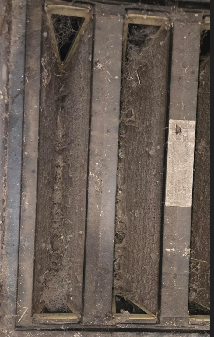
A main filter without a pleat, at the end of a long service interval, looks alarming. The upstream face goes grey, the media packs with barn dust, and the instinct of anyone standing in front of it is that the filter is spent. That instinct is not reliable. Filters pulled looking like this routinely test within specification, because what determines whether a main filter is finished is its pressure drop and its measured efficiency, not how it photographs. The same point runs in the other direction with charged media, where a filter that has lost most of its efficiency looks exactly like a new one.

This matters to the pre-filter decision because the visual argument gets used to make it. A main filter loaded with dust is offered as proof of what a pleat would have prevented, or as proof that the main is due for replacement. Neither follows from the photograph. Both need a test.

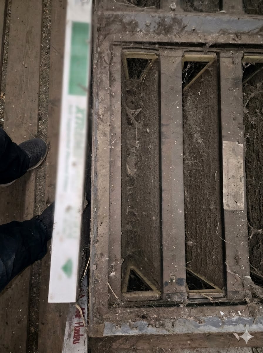
Loaded filter media at close range
Loaded main filter removed from service
Both of these came out of service looking finished. Appearance is not a condition measurement.
Field observation, Dynamic Innovations.

One barn running a seven year main filter life pulled half of its pre-filters at year five to gain airflow. At year seven both groups were tested together. The mains that had run the final two years uncovered showed no significant degradation against the mains that kept their pleats for the full seven. That is two years without a pre-filter at the end of a main filter's life, not a main run uncovered from new, so it does not answer the whole question. It does say that the last two years of pre-filter protection did not show up in the result.

Working the question backwards

Since no one can tell a producer how much life a pre-filter adds to their specific pairing, asking for that number leads nowhere. The useful question is the inverse. Given what the mains cost and what the pre-filters cost to run, how much life would the pre-filter have to add before the arithmetic favours it. That threshold can be calculated exactly, and it is often higher than people expect.

$
years
$/ year
$/ year

Required life multiple
Break-even life, no pleat
Two-stage cost over window
Comparison window

Figures are per main filter, over a window of two main filter service lives. The break-even figure is how long a main filter would have to last with no pleat on it for the two approaches to cost the same. If an uncovered main would outlast that figure, the pre-filters are not paying for themselves on filter cost alone.

What the arithmetic leaves out

Running pre-filters means outside labor at the barn every year. The biosecurity exposure that creates is worth a consideration. The arithmetic on filter cost can be supplied, and it should be run against the real pairing rather than a published average.

Whether a pre-filter pays back depends on your site. We’ll work through yours.

The filter body

What holds the media together has to last as long as the media.

MERV rating gets most of the attention. How a filter is built determines whether that rating survives four to six years of barn service.

Seams and bypass

Face view of a V-bank filter with the header and base seam lines marked
Upstream face. The lines mark the joints where the header and base meet the body of the filter.
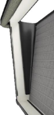
Angled view of a V-bank filter showing the joints between each V and the base
Downstream face. The same joints from the other side, where each V lands on the header and the base.

A V-bank main filter is a plastic-bodied shell containing the pleated media pack. The body is an assembled frame, and every joint in that assembly is a path air can take that does not go through media. A seam that opens even slightly lets unfiltered air pass through the filter body wall. Seams are worth finding and inspecting on any filter, particularly at the header and base, where pressure cycling, humidity swings, and handling all work on the same joint over a multi-year service life. Where seams exist, mechanically fastened and fully potted holds up better than dry-fit and surface-sealed. Fewer face seams means fewer paths to inspect, and a single-piece molded header has none.

Rigidity compounds the seam issue. A filter body that flexes under static pressure deforms the media pack geometry and opens gaps at the media-to-frame interface. Those gaps do not seal when pressure drops, they widen and hold. A rigid, zero-flex body maintains media pack geometry throughout the service life of the filter.

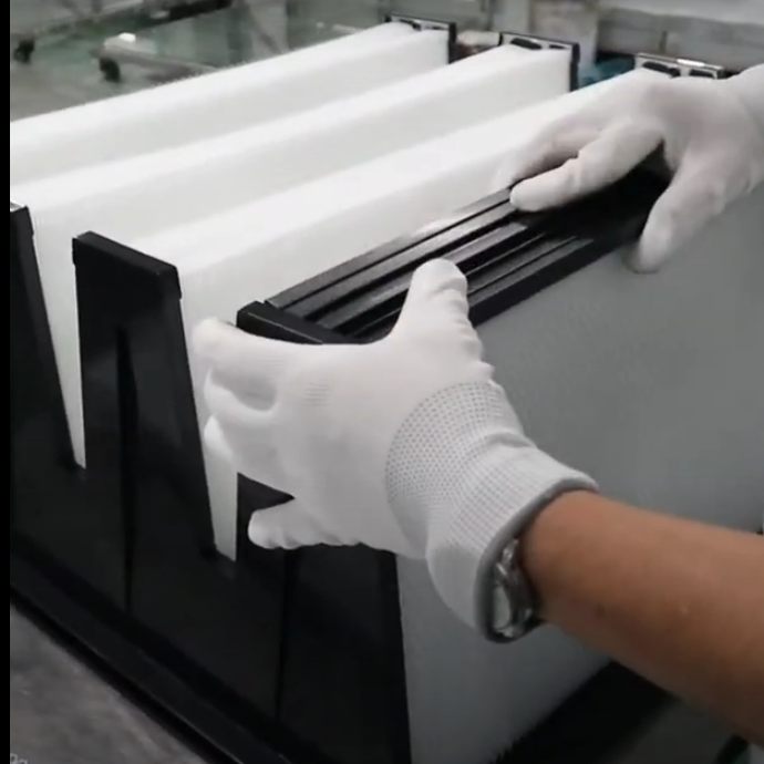
Media pack being seated into a V-bank frame during assembly
Assembly is where the seams are decided. Every joint between frame pieces, and every line where the pack meets the frame, becomes a path to inspect later.
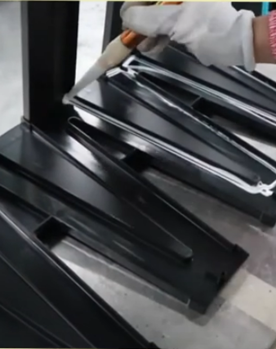
A light bead of potting compound being run into the channel of a filter frame
A light application: a bead run into the channel rather than the channel flooded. Compare against the sectioned filters below.

Potting

Potting is the compound that bonds and seals the media pack into the plastic frame. Complete potting fills the voids between the media edges and the frame interior on all four sides, so all air is forced through the media surface. Where potting is incomplete, the pack can shift or gap at the corners and sides and air routes through those voids unfiltered.

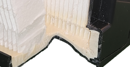
Potting is internal, so it cannot be judged by looking at a finished filter on a walkway. It can be verified, and the check is destructive: cut a sample filter in half and read the section. A sound section shows compound flooding the channel to the edge of the plastic and a continuous fillet where the media meets the frame. Compound sitting below the channel edge still passes while it fills at least half the channel wall. Any section where the back wall of the channel is visible is a failure. Worth knowing: compound applied around the outside of a joint after assembly cannot reach internal voids, so when it is flooded matters as much as whether it is there.

Cut section through a filter edge showing potting between media and frame
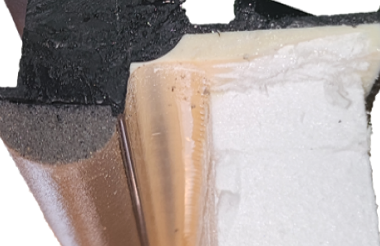
Sectioned edge. The pack is bedded in compound that floods the channel along its full length rather than being tacked at the ends.
Cut section through the base of a V showing the channel flooded with potting compound
Base of a V in section, flooded. Compound carried up the channel wall with no back wall showing is what a passing sample looks like.

Gaskets

The gasket sits on the downstream side of the header, on the flat perimeter face that presses against the holding grid when the filter is seated. Two constructions are common. A poured-in-place gasket cures on the header face as a continuous, form-fit seal with no joints and no adhesive bond. Adhesive-backed and cut foam strip gaskets are applied to the header face and depend on the adhesive bond and on even compression around the full perimeter.

What to look for is the same either way. Check that the gasket sits flat and continuous around the whole perimeter, pay particular attention to corners, and confirm the holding frame compresses evenly across the full face. A gasket lifting away from the header is the condition to watch for. It should not happen on a properly seated gasket, and where it does it points at either the seal or the frame compressing unevenly. Uneven frame compression is a common enough condition in barn installations to be worth checking on any filter.

Cut section through a header corner showing a poured-in-place gasket with potting behind it
Header corner in section. A poured gasket cures in place as one continuous piece, so the seal runs through the corner rather than being joined at it. Potting is visible behind it.

Moisture

Moisture is not an edge case in live animal production, it is a standing condition. Cool cell operation puts saturated air across the media for months at a stretch, humidity runs high by design, and any filter drawing outside air meets rain and blowing snow. Media that softens, sags, or loses pleat geometry when wet does not recover its rating when it dries, and a pack that has shifted stays shifted. The pleat pack has to hold its shape wet, the potting bond has to survive repeated wet and dry cycling, and the frame has to stay dimensionally stable so the gasket keeps even compression through it. Moisture resistance belongs in the specification next to efficiency rather than after it.

Body material and service life

Commodity V-bank filters in the HVAC market are most commonly molded from polypropylene. It is inexpensive and adequate for a 6 to 12 month replacement cycle indoors. Its weakness in barn applications is cold temperature performance. Polypropylene becomes increasingly brittle as temperatures drop, with structural integrity declining significantly at or below freezing. ABS, acrylonitrile butadiene styrene, contains a rubber component that resists impact and fracture rather than shattering. It maintains toughness well below freezing, making it the engineering choice for filter bodies cycling through cold-climate barn attics over multi-year service lives.

This is the core tension in filter selection for livestock. In commercial HVAC, the replacement schedule compensates for construction: a filter built to last 12 months is changed at 12 months and the body never has time to fail. A main filter in a barn installation is expected to perform for 4 to 6 years through ammonia exposure, humidity cycling, freeze-thaw, and shifting static pressure as it loads. A construction standard adequate for 12 months in a climate-controlled building is not adequate for 60 months in a livestock facility. Potting quality, seam construction, body rigidity, and gasket type are baseline requirements for barn service, not upgrade features.

There is now direct evidence of what that body spends those years holding. A University of Minnesota group developed a method to elute viral material from spent commercial filters by grinding the media with liquid nitrogen, then applied it to 44 used MERV 14, 15 and 16 filters pulled from working farms. PRRSV was detected on 27 percent of them and influenza A on 66 percent. The finding worth sitting with is that PRRSV turned up on filters taken from farms that were PRRSV negative when the filters came out. The virus reached the building, the media held it, and the herd never saw it. Most evidence for filtration is a statistic about outbreaks that did not happen; this is the material itself, recovered from the thing that stopped it.Nirmala et al., Journal of Aerosol Science 2021;151:105624. RNA detection; infectivity not tested.

Mounting

Filter walls and attic housings solve the same problem in different places.

Two different structures hold V-bank filters in a swine barn. They appear in different ventilation arrangements with different implications for biosecurity, maintenance, and construction.

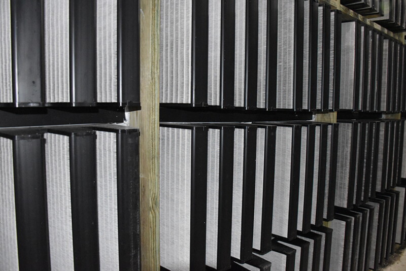
Installed filter wall with V-bank filters seated in grids across a barn endwall
A filter wall in service. Every filter is reachable from the same walkway and the whole bank is inspected in one pass.
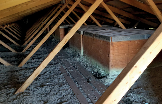
Attic housing built over a ceiling inlet in a barn attic
A housing over a ceiling inlet. Filtration sits at the last point before the animal space, so the attic around it stays unfiltered.

Filter walls and grids

A filter grid is the structural frame that holds one or more V-bank filters and mounts to the wall framing of the barn. Multiple grids assembled together form a filter wall, a bank spanning an endwall or sidewall that treats all incoming air as a single filtered supply. A building can carry more than one bank where airflow or layout calls for it, which keeps every filter reachable from ground level and keeps the number of places to monitor low. Air passes through the filter wall, the attic becomes the clean air plenum, and that clean air distributes through ceiling inlets into the animal space. Filter walls work in both negative and positive pressure systems. The system type determines fan placement and direction, not whether a wall approach is used.

A filter wall concentrates all filtration at one sealed bank. Bypass risk is concentrated at the wall-to-structure seal, one location to get right and monitor. The attic is clean space, so infiltration through the attic envelope moves through already-filtered air. Filter changes are centralized at the wall and accessible without attic entry. Total filter count also tracks actual building airflow requirements more closely. When filters are calculated per inlet the math rarely produces a whole number, and a wall bank averages that overage across the full assembly rather than rounding up at every individual inlet.

Attic housings

An attic housing is a box enclosure that sits directly over a ceiling inlet. It carries as many filters as that inlet's airflow requires, one on a small inlet and as many as eight on a large one, and delivers filtered air down through that single opening. The attic stays unfiltered space, so filtration happens at the last point before air enters the barn. Housings go into new construction as often as they go into existing buildings. In a retrofit a housing drops over each existing inlet, seals to the attic framing, and preserves the ventilation layout with minimal structural change. In new construction the same arrangement is specified from the start. Either way the benefit is the same: the attic never has to be sealed and held as clean space.

What the approach asks for in return is distributed access. Each housing seals to the framing and seats a gasket for every filter it carries, and each one is inspected where it sits. That means attic entry and travel to each unit at every service interval, which is why buildings running housings are normally built with catwalks and permanent lighting to make that routine. Changing mains and pre-filters is more labour per filter than pulling them from a walkway at a wall.

Each approach carries its own construction scope. A filter wall is either designed into new construction or built out as a retrofit, and it makes the attic a clean plenum, so soffits, ridge vents and deck gaps are sealed as part of the same job. A housing approach leaves the attic outside the biosecurity system, so that sealing scope does not arise, and puts the work into the housings themselves and the access built to reach them. Which one is the smaller job depends on the building being started with.

Metal: galvanized and stainless

The barn environment carries sulfates, nitrates, chlorides, hydrogen sulfide, and ammonia, and all of it works on metal. Galvanized steel is structurally rigid, holds shape under static pressure, and can be fabricated in custom dimensions, but barn gases attack the zinc coating over time and the first place that shows is at seams and corners. A galvanized part that looks sound on visual inspection can have compromised seams not visible until it is moved or disassembled, and warm humid farrowing environments accelerate the timeline. Stainless holds its geometry across years of ammonia exposure and temperature cycling, keeps the flat seal surface the filter gasket depends on, and does not crack in extreme cold. It costs more, though its strength lets a thinner gauge carry the same load, so a stainless part is not necessarily heavier than the galvanized one it replaces. For anything that has to hold a gasket flat for the life of the building, stainless is the usual answer.

Plastic: TPO and polypropylene

Neither corrodes, both are chemically inert to barn gases, and both are lighter to handle and easier to field-cut during installation. The difference is how they behave over years of temperature cycling. TPO is durable enough for the service and retains flexibility, which is an advantage in framing that moves with seasonal weather rather than a defect. Polypropylene is more brittle and prone to cracking, and it loses toughness as temperatures drop, which matters in an unconditioned attic. With any plastic, the thing to watch is whether the part stays dimensionally stable enough to hold the filter gasket in uniform compression, since a section under sustained static pressure that flexes or warps opens bypass paths that were not there at installation. Reinforced sidewalls are what keeps a plastic housing from doing that.

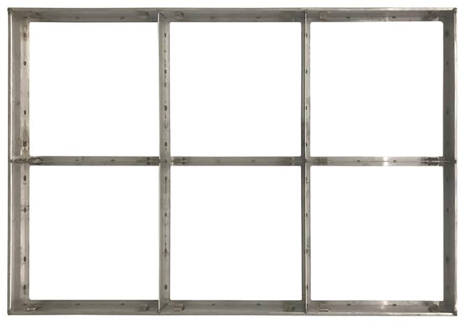
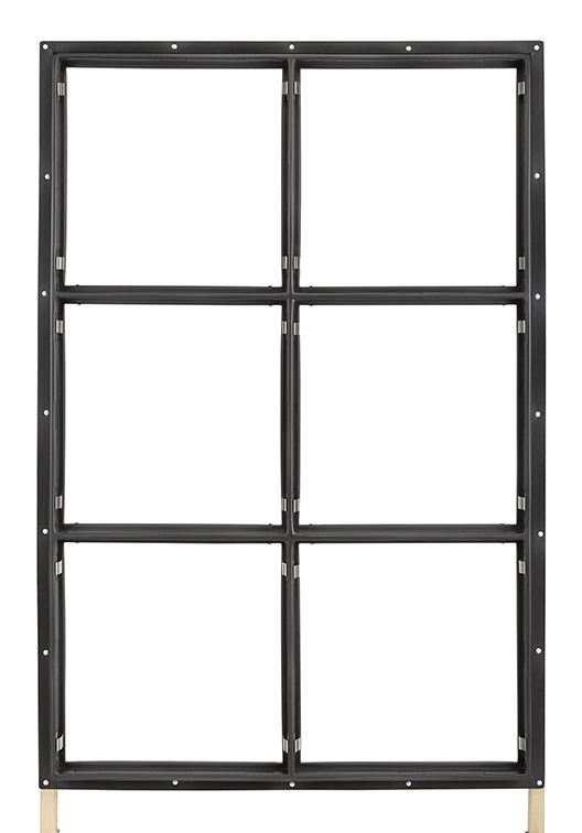
Bare metal filter grid with six openings
A metal grid before filters go in. The seal surface each gasket lands on is the flat face around every opening.
Bare plastic filter grid with six openings
The same job in plastic. Grid geometry follows the building, so cell count and orientation vary with the wall being filled.
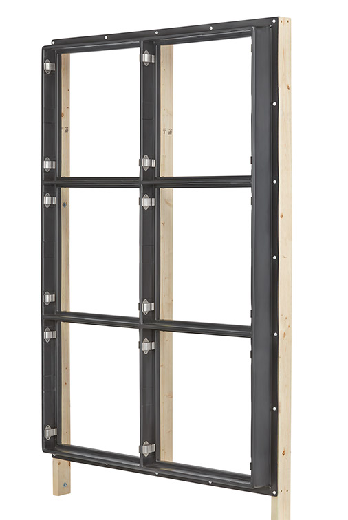
Filter grid mounted to lumber wall framing, seen at an angle
The grid-to-lumber joint runs the full perimeter of the assembly and is sealed on installation, not after.

Whichever material carries the filter, the joint between it and the building is its own detail. Metal and plastic frames both land on lumber, and the sealant at that interface is what closes the last path around the assembly. It has to bond to two dissimilar surfaces, stay flexible while framing moves seasonally, and hold up to washing and barn gases. A correctly built grid or housing sitting on an unsealed frame is bypass with a good filter in front of it.

Every building is different. Send us what you’ve got.

Get in touch

Start with the building you already have.

Whether it is a retrofit, a new build, or a system that has been in for years and is not performing as expected, the conversation starts with what you have.

projects@dynamic-innovations.com 605.237.5869